2013-2018 Kawasaki ZX6R 636 Frame Slider Installation Instructions
WARNING: The installation of all parts in these installation instructions must be performed by a qualified motorcycle mechanic who is using the correct tools and who understands the correct use of all tools required to complete the installation.
Installation Tools you will need:
Torque wrench
8mm Hex/Allen driver (an Allen or hex key will not work)
14mm Socket, Ratchet, and extension
Fairings do not need to be modified (cut) in any way.
1. Remove the left side engine mount screw with the 14mm socket and ratchet with extension. This screw is visible through the cowl opening in the mid fairing (fig A). The fairings on the left side can remain attached to the bike, since the screw can be accessed easily with the fairing in place.
2. Now you can install the left side frame slider. The left side slider is the longest of the two sliders and does not use a bracket. Tighten the supplied screw with your 8mm hex driver and ratchet w/ extension to the factory torque specification (same as factory screw).
NOTICE! PLEASE READ STEP # 3 VERY CAREFULLY. WHEN PROBLEMS OCCUR WITH THIS FRAME SLIDERS INSTALLATION PROCEDURE, 99% OF THEM ARE CONCERNING THIS NEXT STEP, AND ARE DIRECTLY RELATED TO THE INSTALLER NOT READING OR NOT UNDERSTANDING THIS NEXT STEP. READ CAREFULLY. IF YOU DO NOT UNDERSTAND IT OR YOUR MECHANIC DOES NOT UNDERSTAND IT, CALL US BEFORE PROCEEDING WITH STEP 3.
3. On the right side you will see a castle-type nut on a large threaded stud. At the end of that stud you will see the 14mm hex head of the engine mount screw (CIRCLED, fig B). The castle-type nut is the lock nut for the engine mount adjuster and does not need to be loosened. At a glance, it may appear that the engine mount screw and the stud are one, but the stud is hollow and the engine mount screw runs through it. Remove the screw with your 14mm socket. REMOVE ONLY THE ENGINE MOUNT SCREW, DO NOT LOOSEN THE ADJUSTER. The right side bracket and slider come assembled for shipping purposes. You will need to remove the slider from the bracket with your 8mm hex driver and ratchet w/extension.
4. Install the right side bracket using the supplied screw with lockwasher making sure the lockwasher is in the recess of the bracket and bracket is facing away from the engine mount (as shown in figure C). Retain the factory screw for use if the sliders are removed. Adjust the bracket directly over the plastic plug in the frame (ARROW, fig B), then final tighten the bracket-to-engine mount screw. Tighten the screw to the factory torque specification (same as factory screw).
5. Attach the frame slider to the offset bracket. Although the screw comes with a lockwasher, medium strength (blue) thread locking compound is required on this screw only. Using a torque wrench, tighten to 30 ft/lbs. Note: If you have a crash and damage one side, you can purchase just the side you need on our website. WARNING: THE WASHER MUST BE ON THE SCREW BEFORE INSTALLING THE SLIDERS
If you bought OES Fork Sliders with your frame sliders, the installation instructions are here.
For technical assistance please contact us.
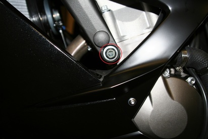
Figure A
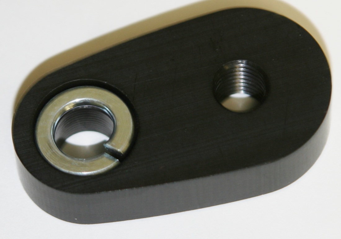
Figure C
|
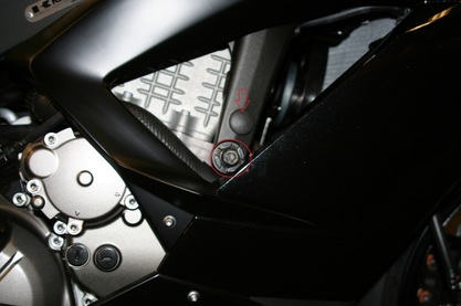
Figure B
|