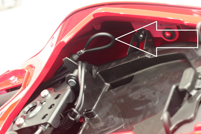
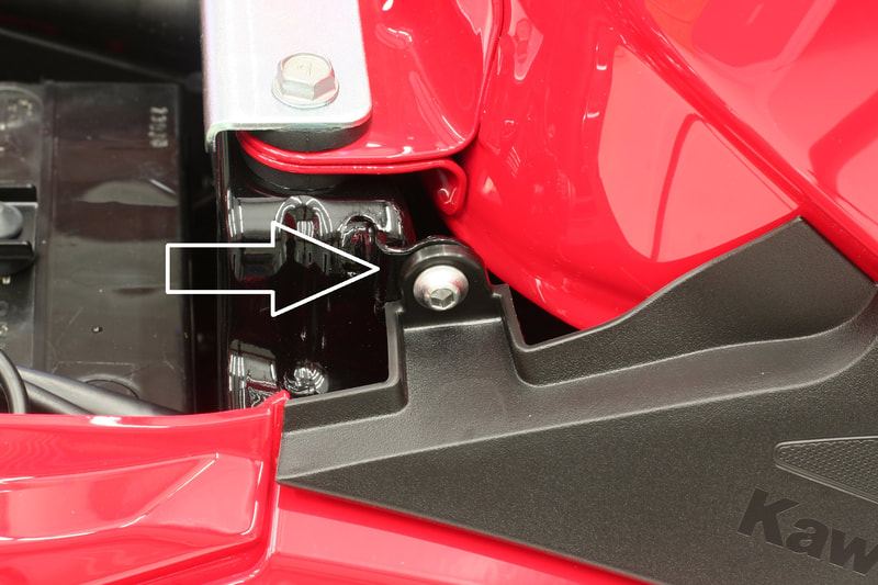
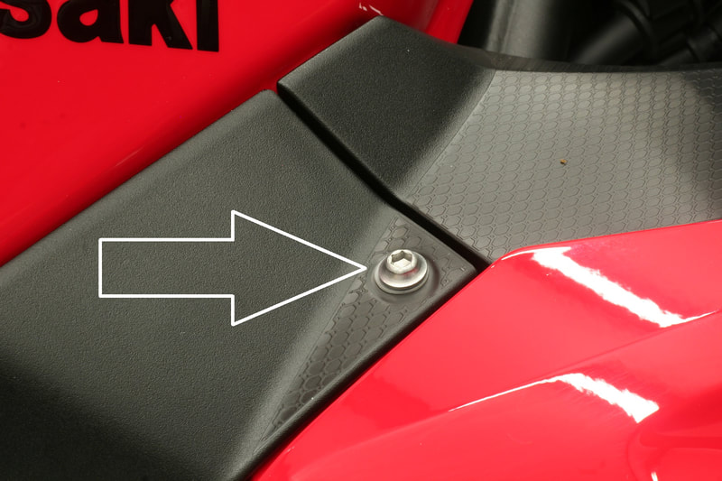
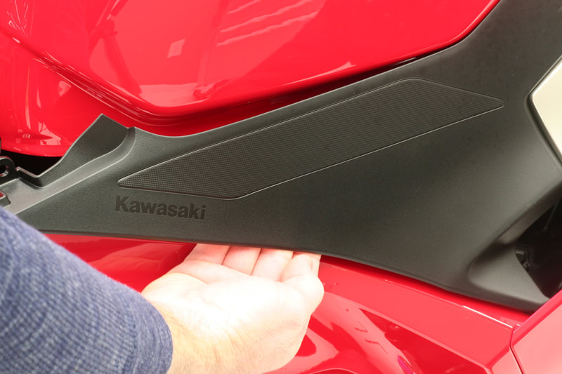
Our frame sliders should be installed by a qualified motorcycle mechanic with the proper tools and training. For a DIY installer, please understand that this is not an easy kit to install and you should plan on spending a few hours with your bike to complete the installation. Although we do not have one, there are some good videos on Youtube that will help you better understand the details of the fairing removal/installation.
1. Remove the passenger seat with the key.
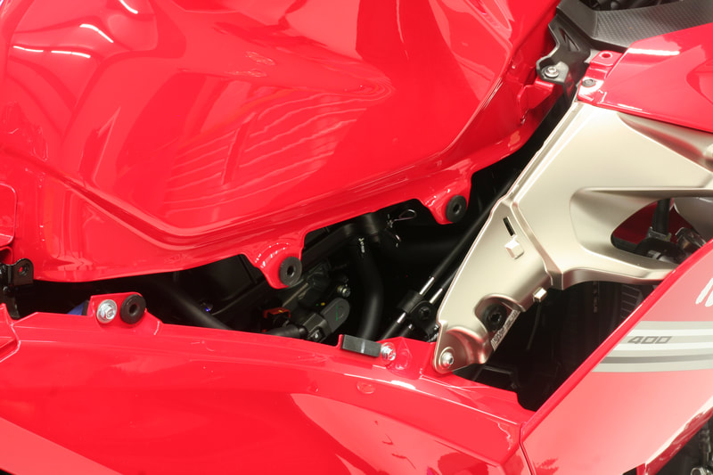
2. Remove the rider seat by pulling on the plastic loop underneath the passenger seat (shown in figure A)
Before proceeding, we recommend taking photos if possible of the fastening points listed in the following steps. Doing so will help you later access important details about the location of the different types of fasteners that are used on this bike.
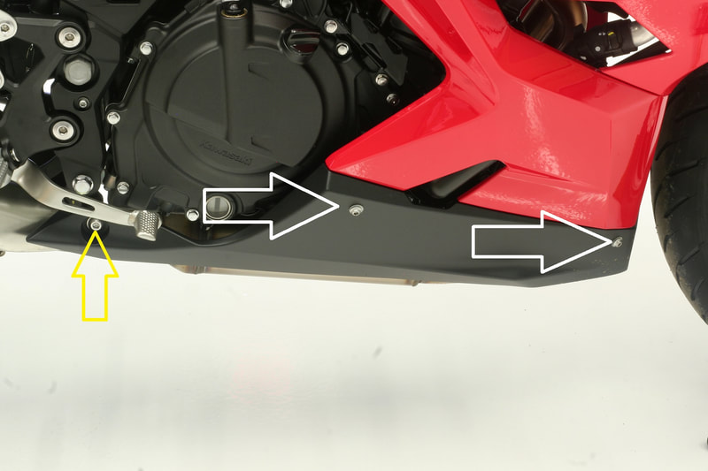
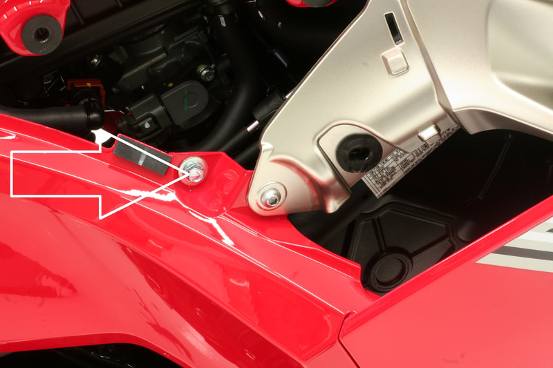
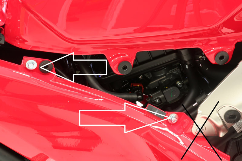
3. Remove the screws on the upper black plastic trim piece (shown in figures B and C )
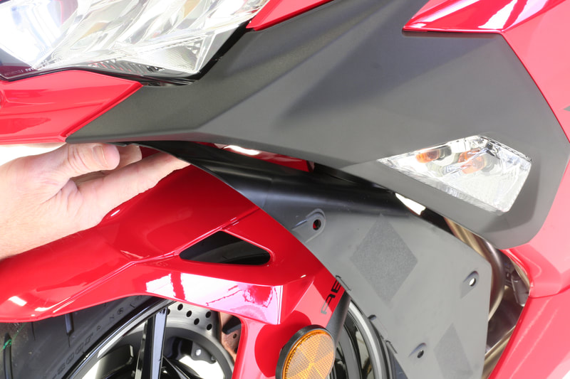
4. Starting from the back of the trim piece, lift up to release the pins shown in figure D. Try to apply your lifting force in the areas of the pins( shown in Figure E) to avoid damage to the trim piece. The front edge has a small tab that needs to be undone from its connection.
5. Remove the pin shown in figure F
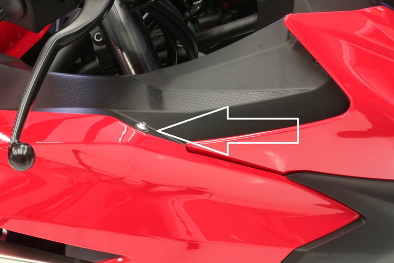
5. Remove the screws shown in figure G.
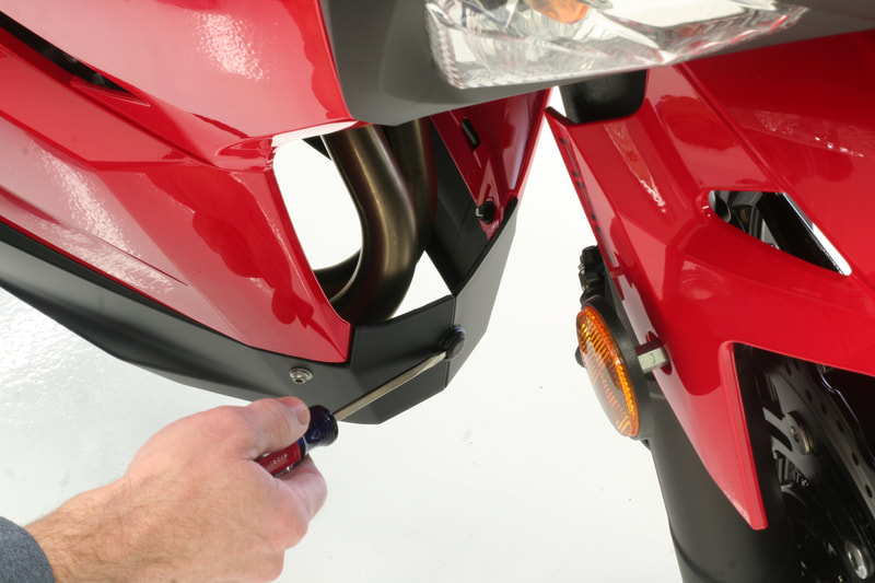
6. The black plastic trim piece that is beneath the headlight and also connected to the inside of the front edge of the fairings needs to be removed by depressing the center of each push pin at the points shown (Figure H ) and removing them from the trim piece. It also has four screws on the front edge beneath the headlight.
7. After the screws are removed, the piece will disconnect from its tabs by sliding it towards the back of the bike.
8. You will need to disconnect each turn signal wire at this step. (also read step 11 for an alternate disconnection technique). The connector is hooked onto a tab. The connector can be slid off the tab easily by pulling it. Disconnect the wires by depressing the tab on the connector. The tab needs a good amount of pressure to release the locking tab. A small screwdriver can also be used to unhook the connector.
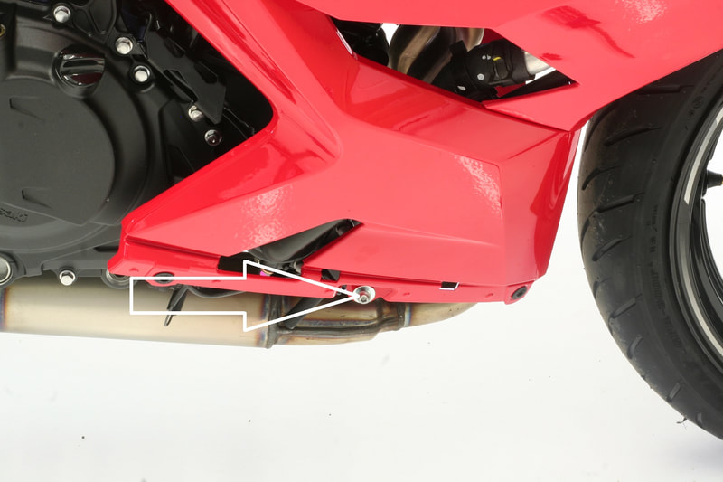
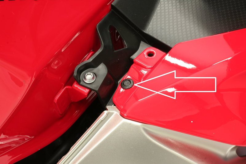
9. The screws shown in figures I, J, K, L, and M need to be removed from the fairing.
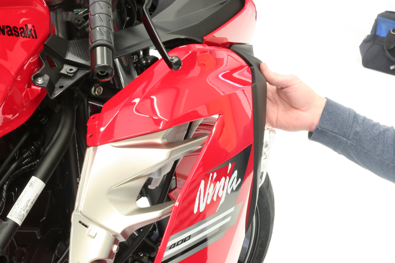
10. Raise the fairing outward to free the tabs at the top edge of the fairing
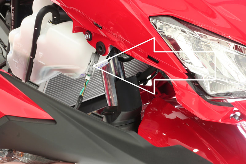
11. If you did not disconnect the turn signal wire in step 8, you can now disconnect the signal wire if you happen to have a helper who can hold the fairing after it is freed of the bike. Connector shown in figure O.
The fairing is now free from the bike and the steps can be repeated for the other side.
Removing engine mount bolts
Only remove one engine mount bolt at a time. If you remove more than one bolt at a time your engine will become misaligned with the frame and realignment will be necessary to complete the installation.
It is also possible, even when removing only one bolt at a time, that the engine will shift slightly. During our design process, we found that supporting the engine with a jack eliminated any misalignment of the engine and frame.
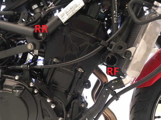
12. Start by removing the right front engine mount bolt shown in figure P with your 14mm socket and ratchet.
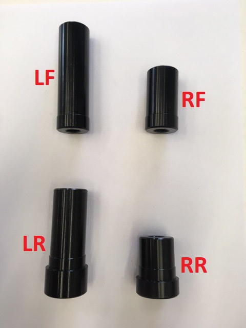
13. Insert the corresponding spacer into the frame where the engine mount bolt was removed.
Note on spacers:
- Our spacers and screws will be wrapped and labeled for the position on the bike. In the event that the spacers become mixed, a photo is shown below for reference. Figure R
- If the spacers are unwrapped only when needed, it will be easier to keep them organized.
14. Insert the 100mm bolt into the hole closest to the wide end of the shorter bracket. The side of the bracket with the machined pockets needs to be facing outward. The wider end of the bracket will be toward the front.
15. Thread the bolt into the hole that the factory engine mount bolt was removed. The bolt should thread into the hole with very little resistance.
If the bolt will not start and turn by hand then the engine has shifted in the frame. This is not common but can happen
sometimes, even if only one bolt at a time was removed. Realignment of the engine mount hole and frame will be necessary before proceeding
16. Thread the bolt into place and tighten snug but not so tight the bracket will not pivot on the bolt.
17. Remove the right rear engine mount bolt shown in figure P.
18. Insert the corresponding spacer shown in figure R.
19. Pivot the bracket to align the hole in the narrow end with the spacer hole and insert the 90mm bolt. The details in step 15 also apply to the rear bolt.
20. Tighten both bolts to the factory recommended torque specification. DO NOT INSTALL THE FRAME SLIDER YET.
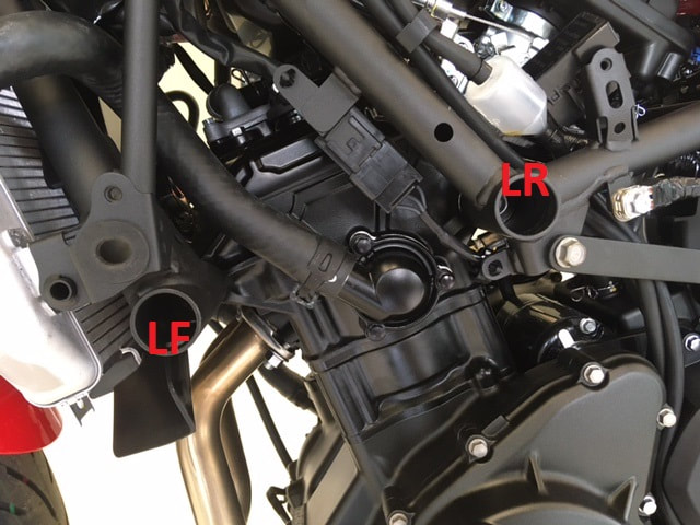
21. Remove the left side forward engine mount bolt at the location shown in figure Q
A spacer is positioned between the frame and the engine. Once the bolt is removed the spacer will fall out of place.
22. Insert our corresponding spacer into the frame where the engine mount bolt was removed.
23. Insert the 130mm bolt into the hole closest to the wide end of the longer bracket. The side of the bracket with the machined pockets needs to be facing outward. The wider end of the bracket will be toward the front.
24. Insert the bolt through our spacer and, holding the factory spacer in place between the frame and engine, push the bolt the rest of the way through and begin threading the bolt into place.
25. Thread the bolt into place and tighten snug but not so tight the bracket will not pivot on the bolt.
26. Remove the left rear engine mount bolt shown in figure Q. A factory spacer is also positioned between the frame and the engine.
27. Insert the corresponding spacer shown in figure R.
28. Pivot the bracket to align the hole in the narrow end with the spacer hole and insert the 120mm bolt through our spacer and the factory spacer positioned between the frame and the engine.
29. Tighten both bolts to the factory recommended torque specification. DO NOT INSTALL THE FRAME SLIDER YET.
30. Once the left side bracket bolts are torqued, a jack used for support of the engine should be removed.
31. Re-install the fairings on the bike. Refer to all photos or notes taken to ensure the screws and clips are put back into the factory positions.
32. Install each frame slider using blue thread locker on our supplied screws. The screws must have 1 lock washer and 1 flat washer on each.
Each slider will be wrapped with its screws and washers in the slider. WARNING: THE WASHERS MUST BE ON THE SCREWS BEFORE INSTALLING THE SLIDERS
33. Tighten each slider to the bracket at 20 lbs/ft with your torque wrench.
