2006-2007 GSXR 600/750 Frame Sliders Installation
WARNING: The installation of all parts in these installation instructions must be performed by a qualified motorcycle mechanic who is using the correct tools and who understands the correct use of all tools required to complete the installation.
Tools you will need:
Torque wrench
Ratchet
Extension
8mm Allen/hex driver
4mm Allen/hex key
Small Phillips screwdriver or other pointed tool
A 1-1/8" hole will need to be cut in the left side fairing- you will need these other tools if that has not been done already.
Drill
1-1/8 hole saw
Small drill bit (1/8 or close to 1/8)
Exacto knife or sharp razor
OES special alignment tool
Notice: Only one side at a time should be installed.
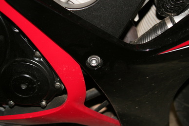
1. Start on the right side (fig.A) by removing the engine mount bolt, which is the bolt that is visible through the hole in the fairing. Use your ratchet and 8mm hex driver to remove the bolt.
WARNING: THE WASHER MUST BE ON THE SCREW BEFORE INSTALLING THE SLIDERS
2. The right side frame slider is the shortest of the two. Start the bolt by hand first to insure proper thread engagement, then tighten with the ratchet and 8mm hex driver.
3. If using a torque wrench, tighten to factory specifications (same as factory screw).
Left side
1. Remove the left side fairing. The fairing has two push pins on the inside near the radiator that hold a small plastic panel to the inside of the fairing- those should be removed first. Push in on the center of the pin to release it, then pull out on the whole pin to remove from the panel. Two other push pins will need to be removed from the underside front point where the left and right sides come together. The fairing has three small bolts at the top edge where it meets the upper fairing, and one bolt near the kickstand. It is also held in place by locator pins on the fairing, which you can just pull out on the fairing to release. The fairing has a few tabs on the top edge- it should be angled outward at the bottom so the tabs can slide out of their slots. After those few steps, the fairing should be free to lay aside.
2. Remove the engine mount bolt with your ratchet and 8mm hex driver.
Alignment tool function: The alignment tools function is to make a mark on the inside of the plastic at the exact point which the hole will be cut. Since the tool is threaded into the engine mount hole, and the frame slider also mounts at this point, the hole you’ll cut in the fairing will be in precise alignment with the mounting point, assuming you follow the instructions below carefully.
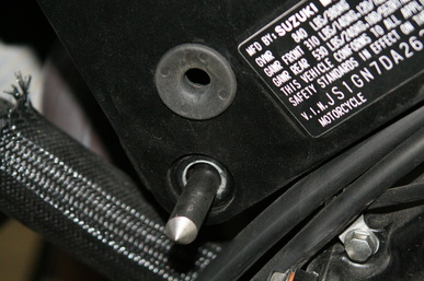
3. Thread the alignment tool into the same hole you just removed the engine mount bolt(fig.B). The depth at which the tool is screwed into the hole is critical. You should be able to mount the fairing on the bike without the tool interfering with the stock mounting position of the fairing. Also, the tool should not be adjusted so far in that you need to push the fairing in more than 1/4" in order to obtain a mark So, if the tool is adjusted too far out, the fairing won’t mount properly, which will result in a misaligned hole. And, if the tool is in too far, you’ll need to push way in on the fairing before the tool makes contact, which will also result in a misaligned hole. The tool can be accessed from the back opening in the fairing, and with a pair of pliers, the tool can be adjusted in or out. If you set the tool in more than needed before mounting the fairing, then once the fairing is mounted, you can just turn it out until it gets close enough. By pushing the fairing inward at the area of the tool, it can be determined if the tool is set correctly. If you need to push in more than 1/4", it’s too far and should be adjusted outward.
Once the tool is adjusted
4. Make sure the fairing is connected by at least two of the top bolts, and the bolt at the bottom near the sidestand. The locator pins (not push pins, leave them out) on the fairing should be fully seated. One of the locator pins is very close to the area the hole will be- this one absolutely needs to be fully seated. The fairing needs to be in its normal mounted position to insure the mark is made in the proper area.
5. In the area of the tool, push inward with medium force- don’t break the fairing, just make a mark on it.
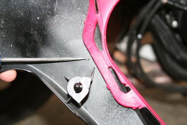
6. Remove the fairing and confirm a mark has been made (fig.C). You’ll probably see other small marks or scratches, but one bigger mark should be noticeable. Remove the tool at this point.
7. At the mark, drill through from the inside of the fairing with the 1/8 drill.
8. At the 1/8 hole, start cutting the main hole (1-1/8) starting from the OUTSIDE (painted side) of the fairing. Make sure to use a sharp hole saw.
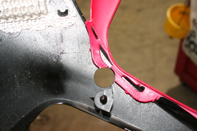
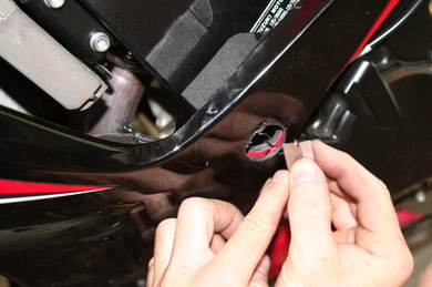
9. When the hole is cut (fig.D), use an exacto knife or sharp razor to clean the edges of the hole (fig.E).
10. After the hole is finished, install the fairing completely- if all went well, you’ll notice that the hole is directly in line with the engine mount bolt hole.
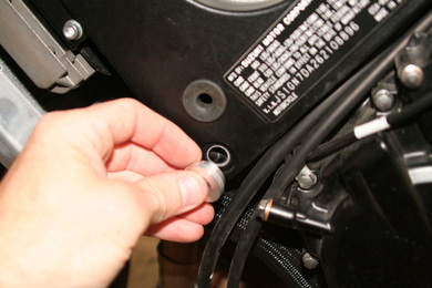
11. The left side slider is longest and uses an aluminum spacer at the base (fig.F) - the slider, bolt, and spacer will be assembled together when shipped. Through the hole, you’ll be able to attach the slider to its mounting point. Using a torque wrench, tighten the bolt to the factory torque specification (same as factory bolt).
If needed, a single side can be purchased on our website
For technical assistance, please contact us.
Thank you for using OES Frame Sliders!
