2009-2015 CBR600RR Installation Instruction for:
Frame Sliders
Bar Ends
Swingarm Spools
WARNING: The installation of all parts in these installation instructions must be performed by a qualified motorcycle mechanic who is using the correct tools and who understands the correct use of all tools required to complete the installation.
Frame Sliders
These instructions explain the installation of OES frame sliders on the 2009-2015 Honda CBR600RR. The instructions
are based on the use of our special alignment tool to be used to mark the fairings in preparation for cutting the frame
slider hole. The tool is not automatically included with the frame sliders set, since different methods are used to cut the
fairings by different installers.
1. Start on either side of the bike (work on one side at a time) by removing the side fairing.
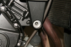
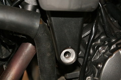
2. Locate the forward engine mount (pictured with bolt removed). The mount is directly forward of the stator cover on the left side,
and directly forward of the clutch/timing cover on the right side.
3. Remove the factory engine mount bolt (17mm socket and ratchet)
4. Install the alignment tool in place of the engine mount bolt. Thread it in most of the way.
5. Install the fairing. Make sure the fairing is installed fully- installing the fairing improperly will result in a misaligned hole
in the fairing.
6. Adjust the tool outward until it makes contact with the inside of the fairing.
7. Push inward on the fairing, directly over the point of the tool. This will make a mark on the inside of the fairing,
indicating where the fairing needs to be cut.
8. Remove the fairing
9. At the mark, drill a 1/8" or smaller pilot hole through the fairing, drilling from the inside out.
10. Use a hole saw that has a pilot drill in the center. The saw should be slightly larger (no more than 1/8") than the
frame slider diameter.
11. Remove the alignment tool.
WARNING: THE WASHER MUST BE ON THE SCREW BEFORE INSTALLING THE SLIDERS
12. Install the frame slider (left side is 1/2" longer) using a 10mm hex (Allen) socket and a torque
wrench set to the factory torque specification (same as factory screw).
13. Re-install the side fairing.
Repeat the steps on the opposite side.
Special Note:
* If you have a crash and damage one side, you can purchase just the side you need by contacting us or by purchasing
directly from our website.
Bar Ends
1. Remove the existing bar ends.
The inside of the bar should have a notched insert that matches the shape of the base of the bar end; our bar ends are made to fit a factory setup and will not work with a generic insert or any type of aftermarket race clip-on bars.
2. Apply a small amount of blue or red thread locker (Loctite) to the supplied screws.
3. Install the bar end making sure that the bar end notch is correctly mated to the bar insert and add light torque with a 5mm Allen wrench. If the bar end appears crooked it may indicate that the notch on the bar end and bar insert are not aligned correctly.
4. Confirm that the bar grip on the throttle side does not touch the bar end and that the bar end does not inhibit smooth throttle twisting action in any way.
We will be more than happy to provide customer support if needed- please contact us
Swingarm Spools
Add a small amount of blue thread locker (Loctite) to the supplied screws and tighten with a light amount of torque using a 6mm Allen wrench.
We will be more than happy to provide customer support if needed. Please contact us.
Frame Sliders
Bar Ends
Swingarm Spools
WARNING: The installation of all parts in these installation instructions must be performed by a qualified motorcycle mechanic who is using the correct tools and who understands the correct use of all tools required to complete the installation.
Frame Sliders
These instructions explain the installation of OES frame sliders on the 2009-2015 Honda CBR600RR. The instructions
are based on the use of our special alignment tool to be used to mark the fairings in preparation for cutting the frame
slider hole. The tool is not automatically included with the frame sliders set, since different methods are used to cut the
fairings by different installers.
1. Start on either side of the bike (work on one side at a time) by removing the side fairing.
2. Locate the forward engine mount (pictured with bolt removed). The mount is directly forward of the stator cover on the left side,
and directly forward of the clutch/timing cover on the right side.
3. Remove the factory engine mount bolt (17mm socket and ratchet)
4. Install the alignment tool in place of the engine mount bolt. Thread it in most of the way.
5. Install the fairing. Make sure the fairing is installed fully- installing the fairing improperly will result in a misaligned hole
in the fairing.
6. Adjust the tool outward until it makes contact with the inside of the fairing.
7. Push inward on the fairing, directly over the point of the tool. This will make a mark on the inside of the fairing,
indicating where the fairing needs to be cut.
8. Remove the fairing
9. At the mark, drill a 1/8" or smaller pilot hole through the fairing, drilling from the inside out.
10. Use a hole saw that has a pilot drill in the center. The saw should be slightly larger (no more than 1/8") than the
frame slider diameter.
11. Remove the alignment tool.
WARNING: THE WASHER MUST BE ON THE SCREW BEFORE INSTALLING THE SLIDERS
12. Install the frame slider (left side is 1/2" longer) using a 10mm hex (Allen) socket and a torque
wrench set to the factory torque specification (same as factory screw).
13. Re-install the side fairing.
Repeat the steps on the opposite side.
Special Note:
* If you have a crash and damage one side, you can purchase just the side you need by contacting us or by purchasing
directly from our website.
Bar Ends
1. Remove the existing bar ends.
The inside of the bar should have a notched insert that matches the shape of the base of the bar end; our bar ends are made to fit a factory setup and will not work with a generic insert or any type of aftermarket race clip-on bars.
2. Apply a small amount of blue or red thread locker (Loctite) to the supplied screws.
3. Install the bar end making sure that the bar end notch is correctly mated to the bar insert and add light torque with a 5mm Allen wrench. If the bar end appears crooked it may indicate that the notch on the bar end and bar insert are not aligned correctly.
4. Confirm that the bar grip on the throttle side does not touch the bar end and that the bar end does not inhibit smooth throttle twisting action in any way.
We will be more than happy to provide customer support if needed- please contact us
Swingarm Spools
Add a small amount of blue thread locker (Loctite) to the supplied screws and tighten with a light amount of torque using a 6mm Allen wrench.
We will be more than happy to provide customer support if needed. Please contact us.


