2017-2024 FZ-10 MT-10 Installation Instructions For:
Frame sliders
Fork Sliders
Swingarm Spools
WARNING: The installation of all parts in these installation instructions must be performed by a qualified motorcycle mechanic who is using the correct tools and who understands the correct use of all tools required to complete the installation.
Tools needed:
- Torque wrench
- 3/8 or 1/2" drive ratchet
- 8mm hex driver
- 10mm hex driver
- 6mm hex (Allen) keys (2)
Also an installation video at bottom of page
Frame Sliders
1. Start on the right side of the bike (do not loosen both sides at once) by removing the engine mount screw. This is the screw that goes through the frame and into the side of the engine. The screw uses the 8mm hex driver to loosen. The screw is circled in red in the photo below (figure A).
Warning! Do not remove/omit the three piece tapered spacer set that is beneath the right side factory mounting screw. The two inner spacers will normally stay positioned correctly once the factory screw is loosened and removed but the outer cone-shaped spacer will usually fall out of place or come out with the factory screw. See figures C & D for a look at the spacers. The spacers serve a critical role in proper mounting of the engine and should not be omitted under any circumstance.
2. Identify the right slider- it is the shorter slider.
WARNING: THE WASHER MUST BE ON THE SCREW BEFORE INSTALLING THE SLIDERS
3. Our frame slider screw is driven by a 10mm hex driver. Do not use any type of impact wrench to install the slider screw. Tighten the screw to the factory torque specification (same as factory screw).
4. Make sure the right side is tight before starting on the left side.
5. On the left side, remove the engine mount screw (figure B) using the 10mm hex driver and install the longer frame slider using the same method and torque as the right side. The spacer set is not a factory part of the left side mount.
Fork Sliders
Items needed:
- 5mm Hex/Allen wrench (2)
- Blue thread locker (Loctite)
- Red thread locker (Loctite)
1. Apply a small amount of red thread locker to the screw threads of the longest
screw that was supplied with the fork sliders set.
2. Attach the long slider to the aluminum fork slider rod.
3. After tightening, insert rod/slider assembly into the right side of the axle. The
slider base should fit into the axle.
4. Apply blue thread locker to the short screw in the set and install the remaining slider onto the left side. It may take a second to find the rod in the axle and get the threads started but just be sure the screw
starts straight.
5. Hold the screw on the opposite side with another 5mm hex wrench and tighten
the left side with a small amount of torque. CAUTION!!!! The threads in the rod
will strip if too much force is applied to the screws when tightening.
The fork slider assembly should not have any lateral movement once tightened.
Swingarm Spools
The spools mount to the swingarm- the arrow in figure B points to the recommended mounting point.
1. Apply a small amount of medium (blue) thread locking compound to each spool screw.
2. Tighten with light torque with the 6mm Allen Key.
If one side is damaged in a crash or drop, we offer single side replacements, instead of buying a complete set.
For technical assistance, please contact us.

Figure A
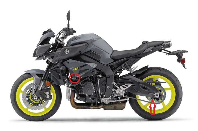
Figure B
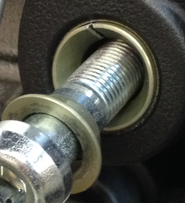
Figure C
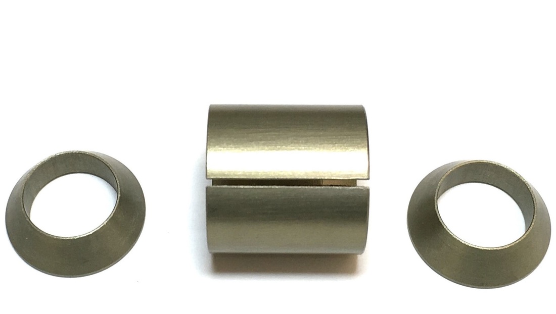
Figure D