2017-2020 R6 Installation Instructions for:
Frame Sliders
Fork Sliders
Rear Axle Sliders
Swingarm Spools
WARNING: The installation of all parts in these installation instructions must be performed by a qualified motorcycle mechanic who is using the correct tools and who understands the correct use of all tools required to complete the installation.
Frame Sliders
Tools/Items Needed:
Torque wrench
1/2" drive ratchet
12mm socket
5mm Allen wrench
4mm Allen wrench
8mm Allen driver
Phillips screwdriver (small)
Blue Loctite
Not necessary but a helper is nice to have for this installation.
Frame Sliders
Fork Sliders
Rear Axle Sliders
Swingarm Spools
WARNING: The installation of all parts in these installation instructions must be performed by a qualified motorcycle mechanic who is using the correct tools and who understands the correct use of all tools required to complete the installation.
Frame Sliders
Tools/Items Needed:
Torque wrench
1/2" drive ratchet
12mm socket
5mm Allen wrench
4mm Allen wrench
8mm Allen driver
Phillips screwdriver (small)
Blue Loctite
Not necessary but a helper is nice to have for this installation.
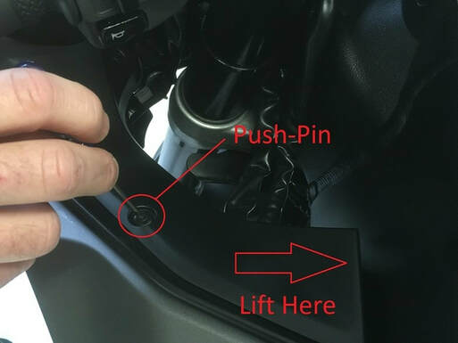
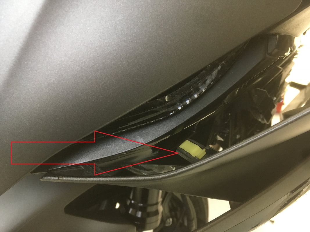
1. Remove this trim piece by removing the two push-pins on the trim piece. The pins will unlock and remove by depressing the center of each with a small screwdriver tip.
CAUTION: The trim piece also has a pin (not a push-pin) that holds it to a bracket. That pin (see figure B) is located at the end of the piece near the frame. A lifting force needs to be applied near the pin to free it from the bracket. If the piece is lifted from the front DAMAGE TO THE TRIM PIECE WILL OCCUR.
For easy removal after the pin disconnects from the bracket, the piece needs to be shifted backward slightly, then tilted out.
|
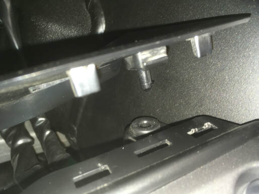
Figure B
|
2. The trim piece here will also need to be removed. It has four push-pins (only two are visible in the photo).
|
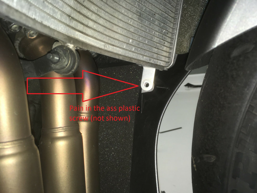
3. After that, you'll need to remove the pain in the ass plastic screw that holds the fairing to the radiator. The screw is not shown.
Yours might not give you trouble but if it does we recommend using a small screwdriver and very light pressure to unscrew it. You also might need to hold the outermost part of the flange to prevent it from turning. We'll gladly revise these instructions to include any other tricks to remove the screw if submitted.
|
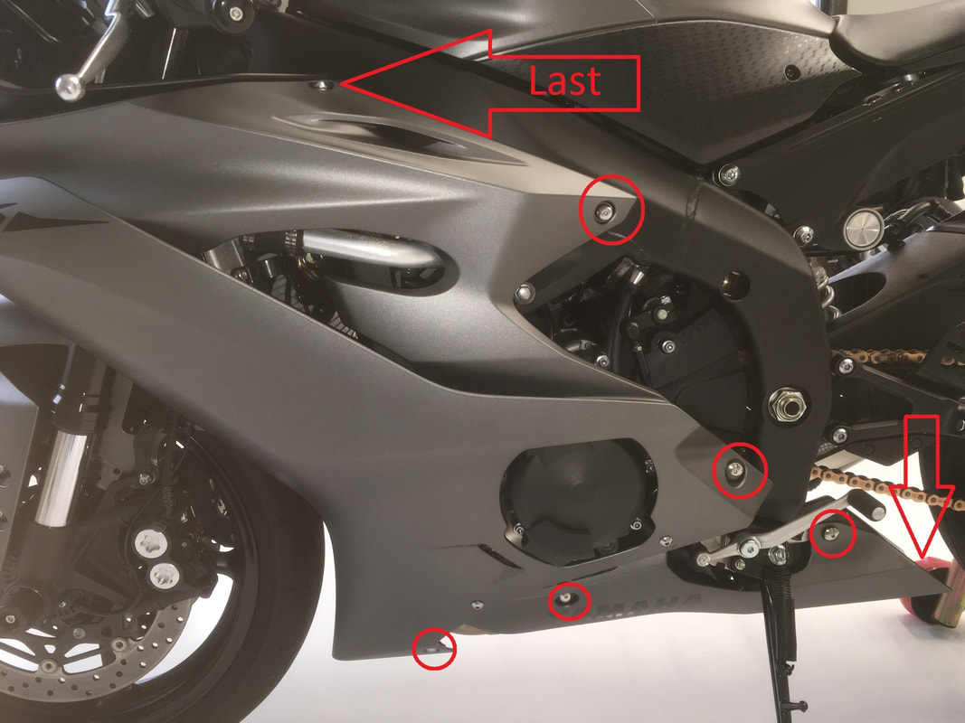
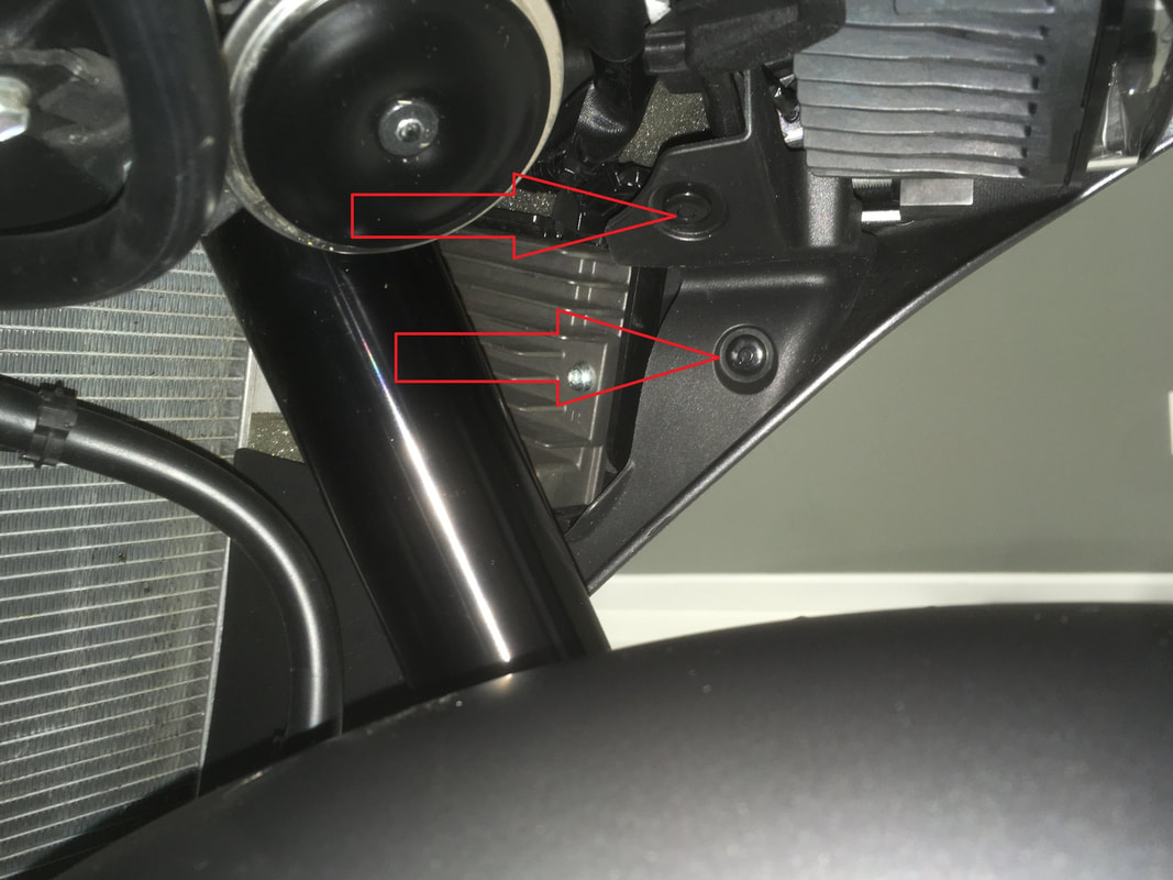
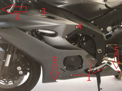
4. Except for the screw at the arrow point labeled 'Last', remove each fairing screw at all other circled points. The arrow pointing down is to a screw that connects the left and right fairings at the rear. Don't forget the screw near the headlight (figure E)- the tab in step five will not release if the screw is not removed.
|
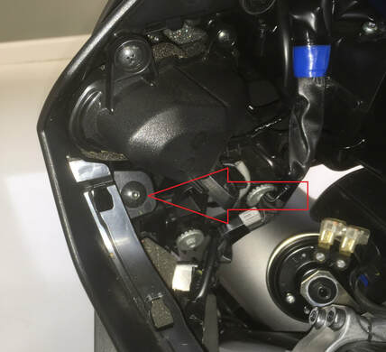
Figure E
|
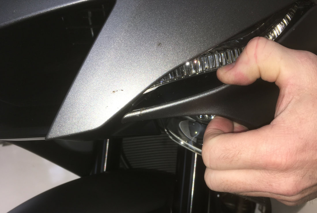
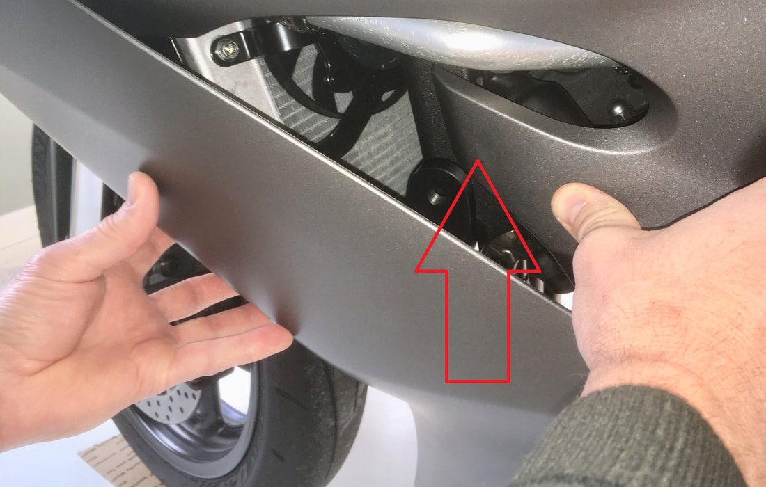
5. Remove the last screw and support the fairing at that point while pulling firmly in the area shown here.
CAUTION: The fairing could possibly be damaged if your pulling force is not applied to the specified area. The connection is tight but a firm pull outward will free it.
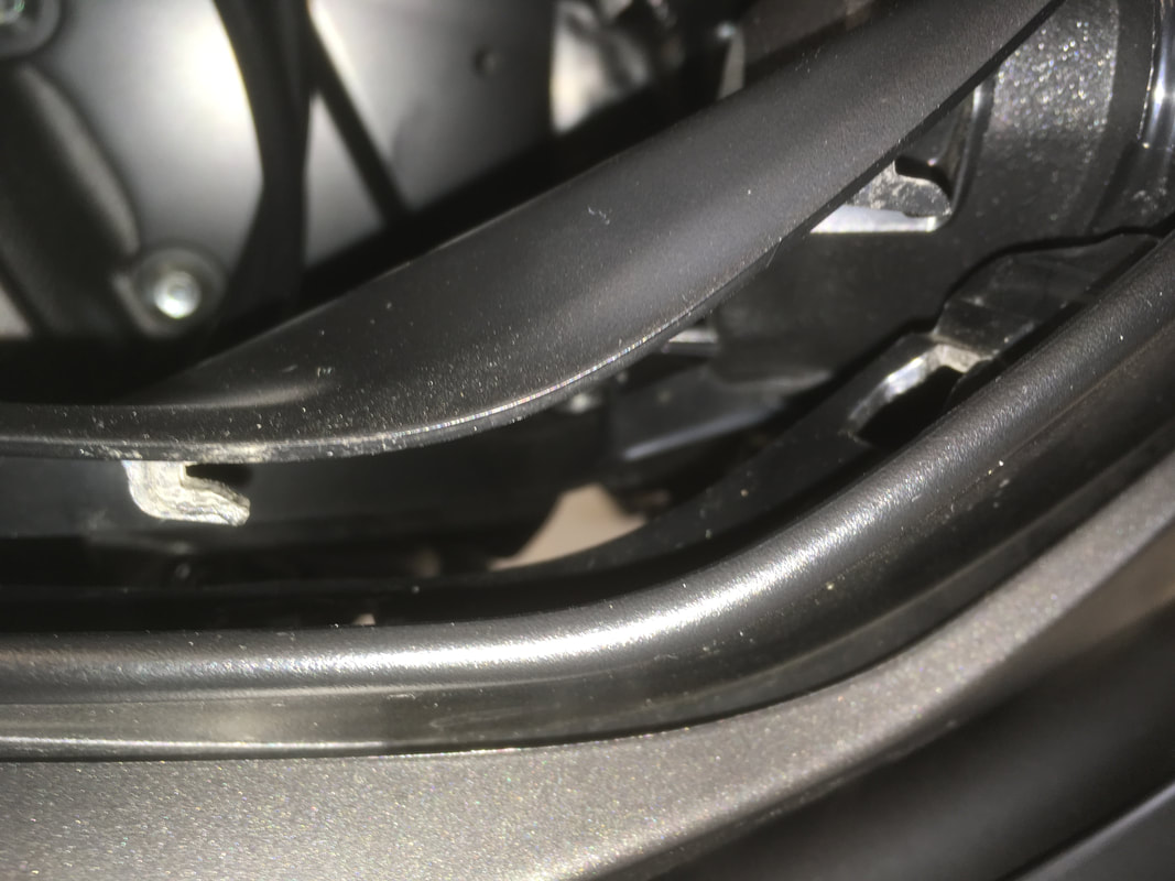
Figure F shows the tab on the fairing that is being disconnected with the correctly applied force.
|
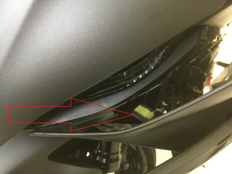
Figure F
|
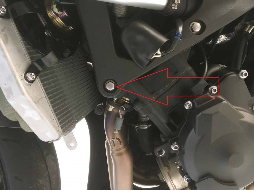
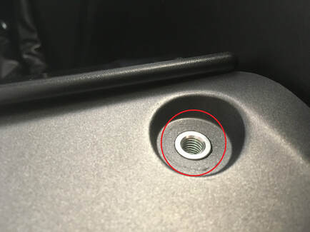
6. With your 12mm socket and ratchet, remove this engine mount screw. No other engine mount screws should be removed while this one is out.
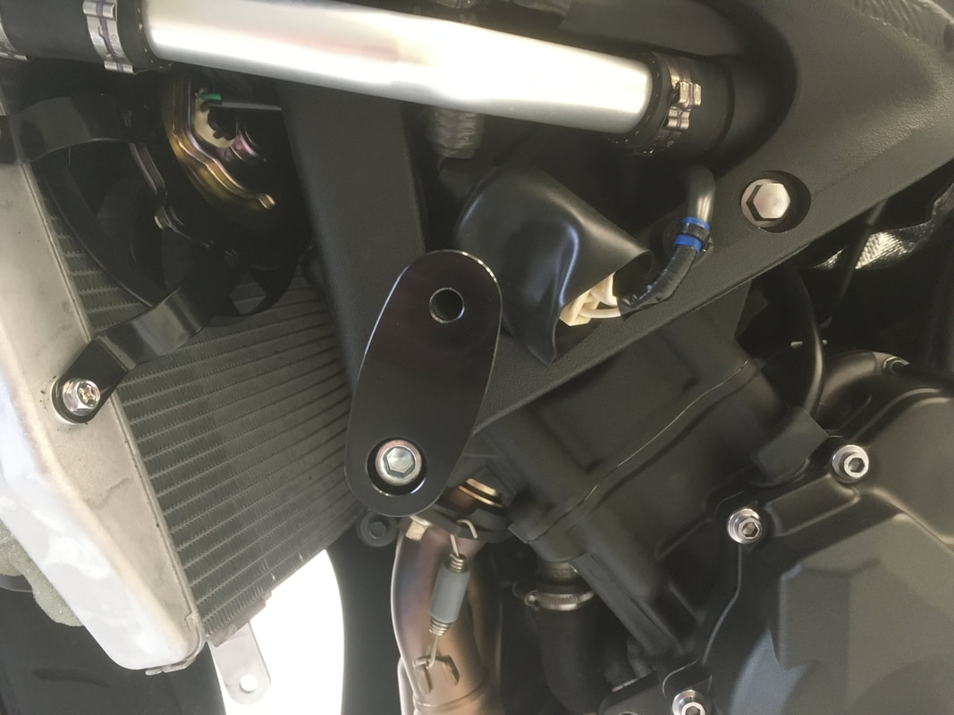
7. Install the offset bracket so that it is near the 1 o'clock position. The R6 in the photo is sitting level on the floor and is being held upright by a helper.
|
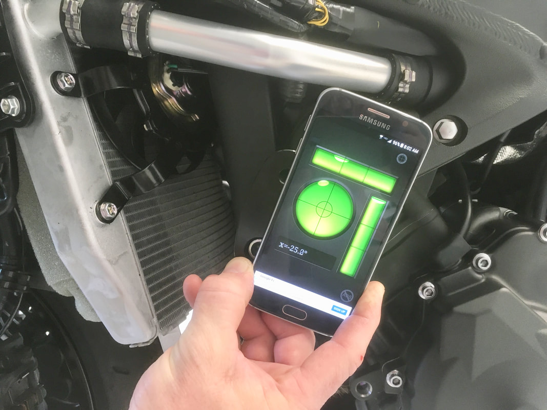
A digital level or a phone with a level app is good to use, as seen here. Once the correct position is achieved, the screw should be final tightened using a torque wrench and the factory specified amount of torque (same as factory screw).The bracket will try to turn but holding it will prevent it from doing so.
|
|
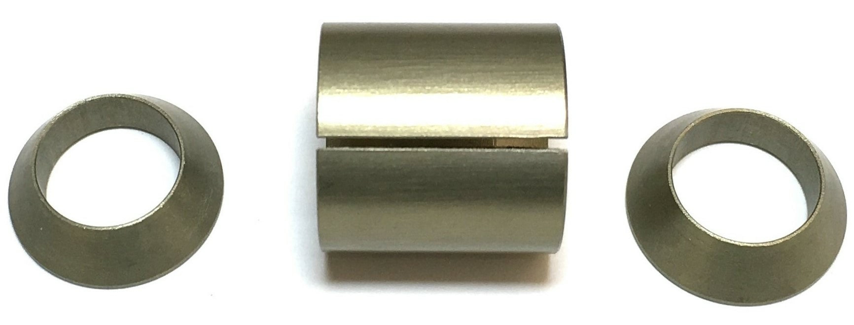
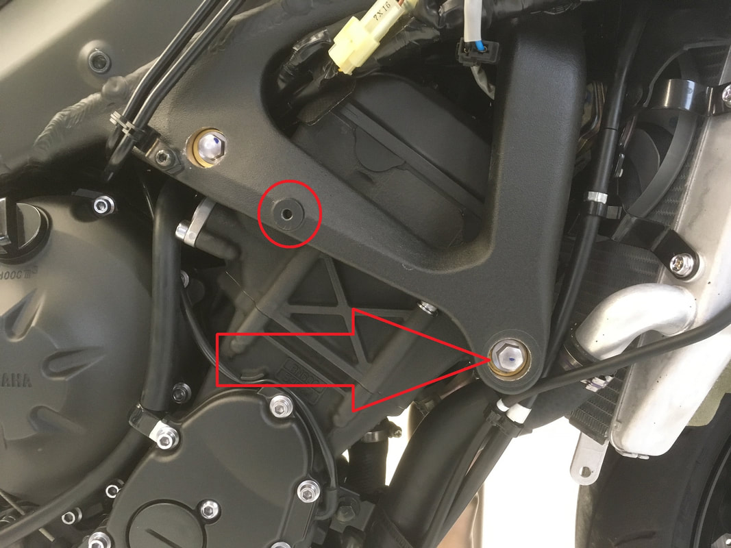
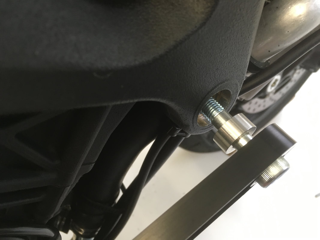
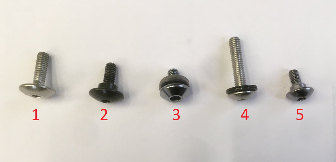
8. The right side fairing should have already been removed, so the engine mount screw at the arrow point can be removed. With your 12mm socket and ratchet, remove the engine mount screw. No other engine mount screw should be removed while this one is out. WARNING! Do not remove the spacer set under the mount screw- it must remain in place. If the spacer set is missing for any reason, do not proceed until a spacer set is installed. A spacer set is shown here for reference if there is any concern of a missing spacer set.
|
9. The supplied frame slider bracket and bracket spacer are shown above. Hand tighten the supplied screw.
|
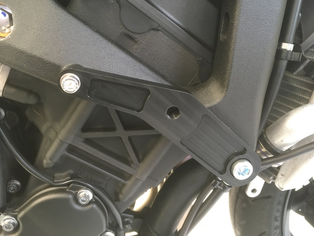
10. Attach the other end of the bracket with the small screw as seen here and hand tighten the screw. Use your 8mm Allen driver and torque wrench to final tighten the larger screw to the factory specified amount of torque (same as factory screw).
Use a 5mm Allen wrench to final tighten the small mounting screw. Over torquing the screw will snap it. We do not have a torque spec for this screw, however, a torque angle of around 45 degrees will be sufficient.
|
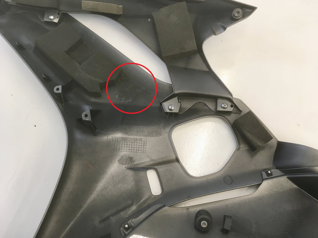
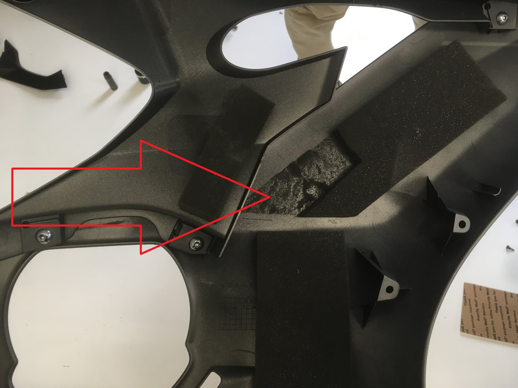
11. These photos show areas of the inside of each fairing that need a small section of the foam removed. When installed, each fairing is very close to the frame slider offset bracket; foam left in these areas will cause each fairing to bulge outward slightly when mounted.
|
|
Just in case you forgot where each fairing screw is supposed to go, use these photos for reference. #2 is the screw near the back of the headlight.
|
|
12. Install the left side fairing. Push on the area shown in figure H to clear the mounting bracket, then move the fairing forward.
|
13. The section at the top of the fairing near the frame needs to be properly seated. The black piece at the top edge of the fairing needs to be connected to the fairing completely- it has a tab that is sandwiched between the fairing and its mounting bracket. It's more accurate to connect the black piece to the fairing first, then put the fairing in place. The mounting point should look just like the one in the photo- if not, the fairing will not tighten correctly here.
|
14. Align the forward mounting tab with its connection then push firmly to lock in place. After that, you can install all of the fairing screws into their correct points mentioned earlier. We recommend checking the left side slider clearance before continuing- if the slider touches the fairing the bracket should be re-positioned.
|
15. After the fairing is tight, install all trim pieces. The right side upper trim piece is shown. The tabs in the photo need to be correctly positioned, then the piece needs to be pushed forward before setting the pin at the back edge of the piece, then install all of the push pins.
|
16. The left side frame slider is slightly shorter than the right side. Apply a small amount of blue loctite to left side frame slider mounting screw and tighten to the bracket using 35 lb/ft of torque. Even when fully tightened, the slider may turn on its spacer with force but this is normal.
17. Repeat step 16 with the right side slider, the longest of the two.
Finish this installation by checking that all fairing screws and pins are tight and in place and that both frame slider mounting screws have been final-tightened.
Please contact us with questions about this installation.
If a frame slider or bracket is damaged in a crash or drop you can purchase just the side you need on this site.