10-13 KAWASAKI Z1000 INSTALLATION INSTRUCTIONS FOR:
-Frame Sliders
-Fork Sliders
-Swingarm Spools
WARNING: The installation of all parts in these installation instructions must be performed by a qualified motorcycle mechanic who is using the correct tools and who understands the correct use of all tools required to complete the installation.
Tools you will need:
Torque wrench
3/8 or 1/2" drive ratchet
14mm socket
6mm Allen key
8mm hex (Allen) driver
medium length extension
NOTE: These sliders bolt directly to the engine mounts of the bike and require no modifications or cutting of the fairings, frame, or any other part of the motorcycle.
The right side of the bike is the side with the throttle, and the left side of the bike is the side with the clutch lever.
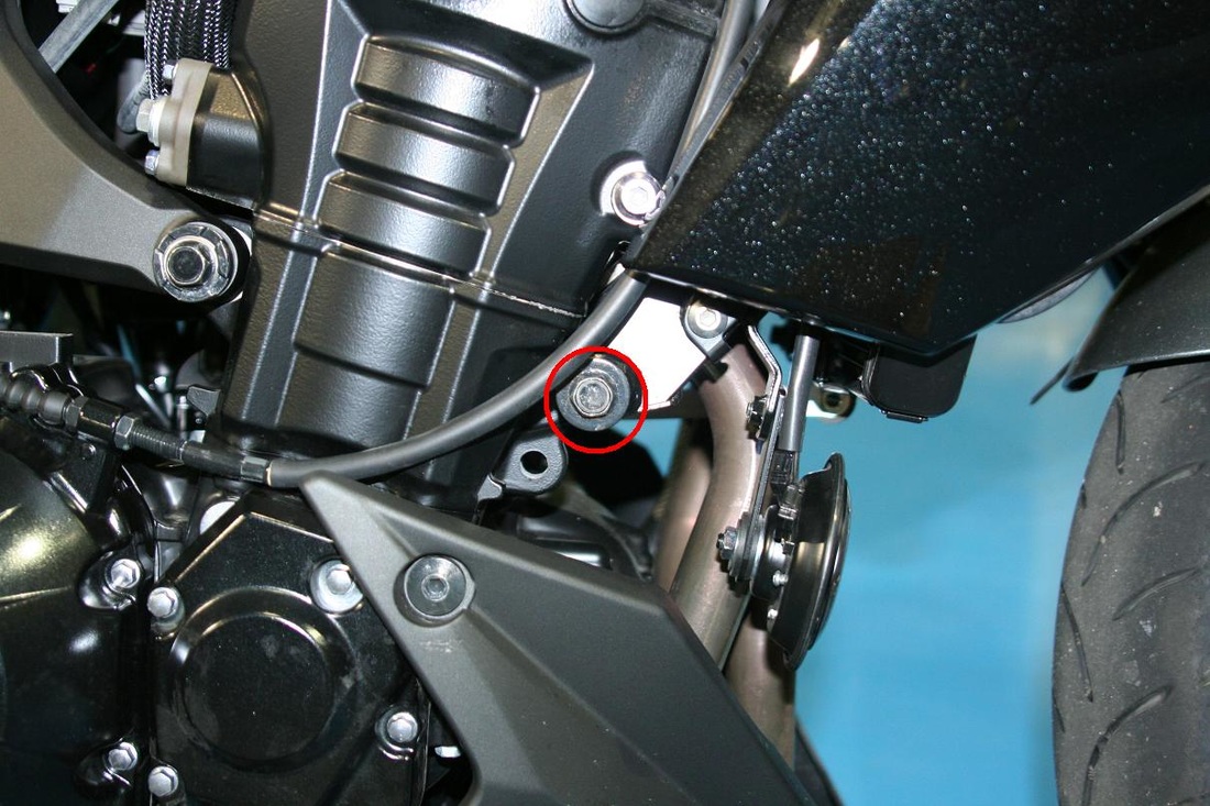
1. Locate the forward engine mount on the right side (fig A). This mount is on the front side of the engine in the area behind the horn. The clutch cable runs very close to the mount (the right side slider is designed differently to allow for clearance of the cable).
2. With the 14mm socket and ratchet, loosen (counter-clockwise rotation when viewed from the side of the bike) the factory engine mount screw and remove it from the engine mount.
3. For the right side, select the slider with the longer, smaller diameter base.
CAUTION: The factory screws use red (high strength) thread locking compound. We strongly recommend using red thread locking compound just as the factory has. In any case where red or blue thread locking compound is not visible on the factory screws, apply nothing to the screws.
4. Insert bolt/washer through slider and install at the mounting point shown. You should feel the threads of the screw engage the threads of the motor mount. There should be little resistance until the screw head contacts the aluminum spacer inside the slider. WARNING: THE WASHER MUST BE ON THE SCREW BEFORE INSTALLING THE SLIDERS
5. Tighten the screw to the factory torque specification (same as factory screw).
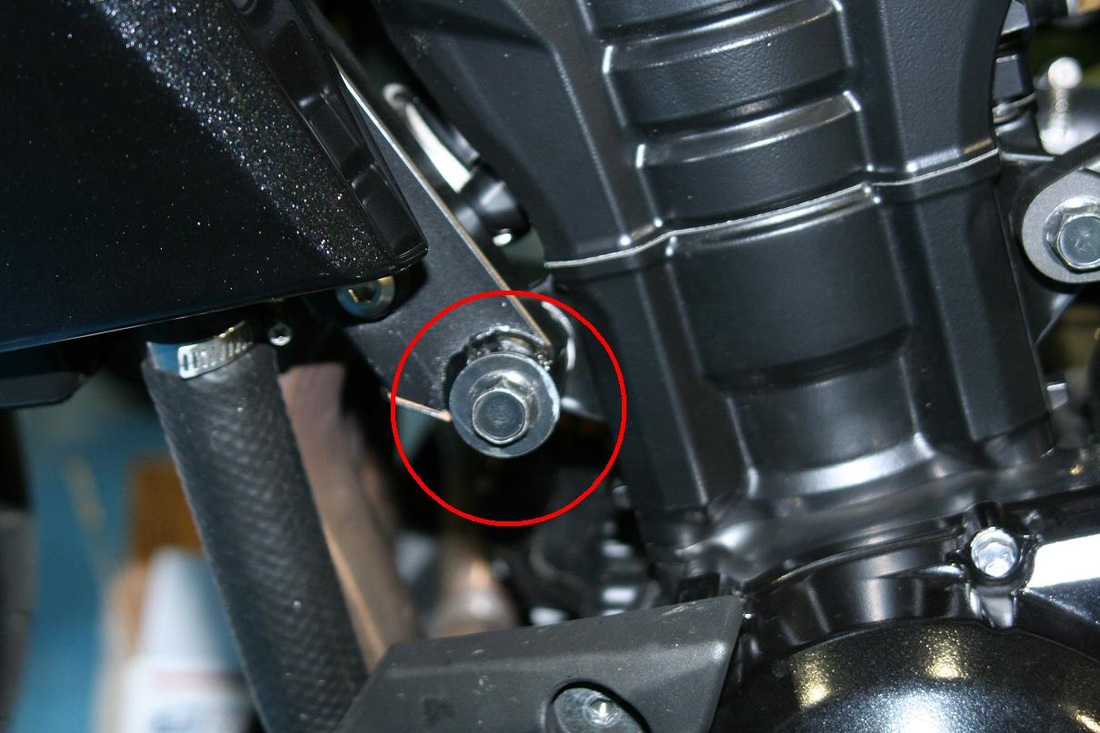
6. For the left side, the mounting point is in the same area of the engine (fig B).
Repeat steps 2-5 to complete the installation for the left side. Remember to use the flat washer beneath the slider and apply thread locking compound to the threads of the screw supplied with the slider.
If you damage one slider in a crash or drop, you can order just the side you need on our website.
For questions regarding installation, please contact us.
Fork Sliders
Note: This set is installed with the front axle in its normal operating position.
1. Apply medium strength threadlocker compound to a mounting screw (w/washer) and attach the slider with the smaller diameter base to the rod.
2. Insert slider and shaft assembly into the left side of the axle.
3. Apply medium threadlocker compound to the remaining screw and insert through the short slider. While holding the opposing slider/shaft firmly in place by hand, insert the slider/screw into the axle and carefully start the screw into the shaft. It may take some careful positioning of the shaft to get the threads started into the shaft.
4. Once the screw has been started and confirmed that proper thread engagement was made, lightly torque the screw.
Swingarm Spools
The swingarm spools are installed with blue thread locking compound and medium torque.
For technical assistance, please contact us


