2009-2012 ZX6R Frame Sliders Installation Instructions For:
- Frame Sliders
- Fork Sliders
- Swingarm Spools
WARNING: The installation of all parts in these installation instructions must be performed by a qualified motorcycle mechanic who is using the correct tools and who understands the correct use of all tools required to complete the installation.
Tools you will need:
- Torque wrench
- 8mm hex/Allen driver
- 4mm & 6mm hex/Allen key or driver
- 14mm socket
- 3/8 drive ratchet
Frame Sliders
* Start on the right side- do not have both side engine mount screws loose at the same time.
* The fairings will need to be partially disconnected, but do not need to be completely removed from the bike.
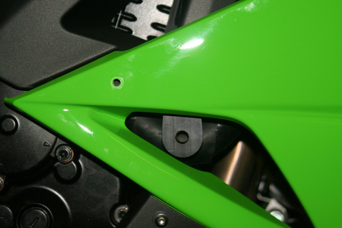
1. On the right side (viewed as sitting on the bike, right is throttle side), remove the 4mm allen head screws at these points (also circled in figure A below):
* At the top part of the fairing close to the frame. While riding the bike, the screw would be below your right arm. The hex key will be in the vertical position while removing/installing this screw.
* At the back section of the mid fairing, just under the cowl opening for the engine.
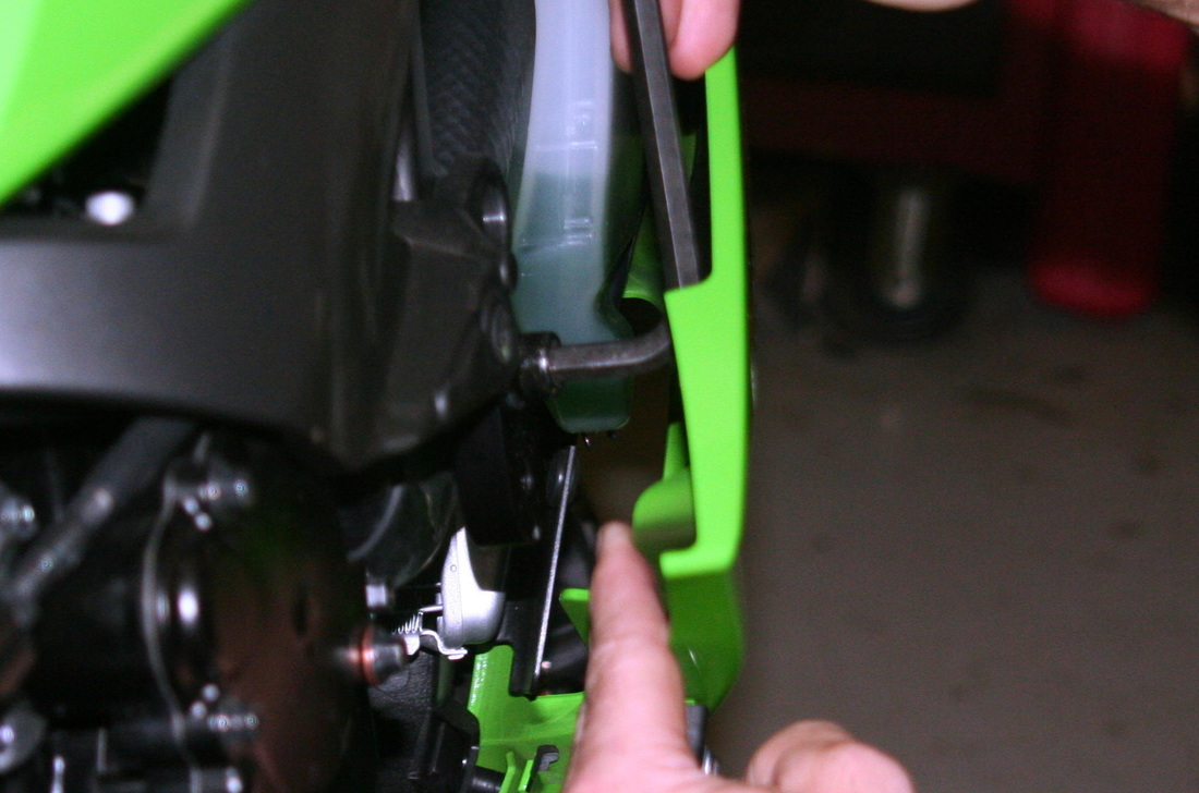
* At the rear area of the lower fairing, just below the rear brake lever. Removing these 3 screws will allow the fairing to flex outward enough (figure B) to gain access to the engine mount screw. This method may require (or will be easier with) a helper.
NOTICE! PLEASE READ THIS NEXT STEP VERY CAREFULLY. WHEN PROBLEMS OCCUR WITH THIS FRAME SLIDERS INSTALLATION PROCEDURE, 99% OF THEM ARE CONCERNING THIS NEXT STEP AND ARE DIRECTLY RELATED TO THE INSTALLER NOT READING OR NOT UNDERSTANDING THIS NEXT STEP. READ CAREFULLY. IF YOU DO NOT UNDERSTAND IT OR YOUR MECHANIC DOES NOT UNDERSTAND IT, CALL US BEFORE PROCEEDING.
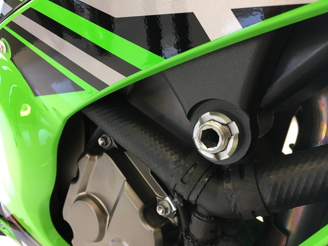
On the right side you will see a castle-type nut on a large stud. This is the lock nut for the engine mount adjuster and DOES NOT need to be loosened. At a glance, it may appear that the engine mount screw and the stud are one, but the stud is hollow and the engine mount screw runs through it. Figure F shows a typical Kawasaki right side engine mount adjuster design with the engine mount screw removed.
2. With the 14mm socket and ratchet, remove the right side engine mount screw.
3. Using the screw provided(M10x1.25x70 HHCS), attach the small offset bracket to the engine mount point. The bracket normally comes assembled with the right side slider but the slider IS NOT FINAL TORQUED and will fall off while riding if it is not tightened with Loctite on the threads. If shipping requires the bracket and slider to be apart, the bracket and slider will be marked as right or left side. The bracket should be pointing down. (figure C)
4. Place the right side frame slider (shorter slider) against the bracket to check the bracket adjustment. If the bracket is adjusted correctly, final tighten the engine mounting screw. Tighten the screw to the factory torque specification (same as factory screw).
5. Install all fairing mount screws that were previously removed.
6. Attach the frame slider to the bracket using the supplied screw with Loctite and final tighten using the 8mm hex driver and ratchet or torque wrench. 30 ft/lbs is the frame slider to bracket torque amount. WARNING: THE WASHER MUST BE ON THE SCREW BEFORE INSTALLING THE SLIDERS
Left Side
1. On the left side (viewed as sitting on the bike, left is clutch lever side), remove the 4mm allen head screws.
* The fairing screws that need to be removed from the left side are the same as the right side.
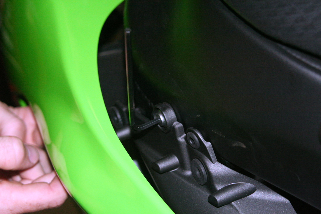
* The left side has a separate plastic piece beneath the fairing. The plastic piece is held on by two screws and needs to be removed and slightly modified to fit the frame slider on the left side, since the piece partially covers the left side engine mount screw. Figure D shows the fairing being held out while the plastic piece is loosened.
2. Remove the left engine mount screw.
3. Using the supplied screw (do not use the factory screw as you did for the right side), attach the left offset bracket and adjust correctly. Tighten the screw to the factory torque specification (same as factory screw). The next step will involve making a slight modification to the plastic piece. The modification does not effect the function of the piece and, if done properly, is not noticeable.
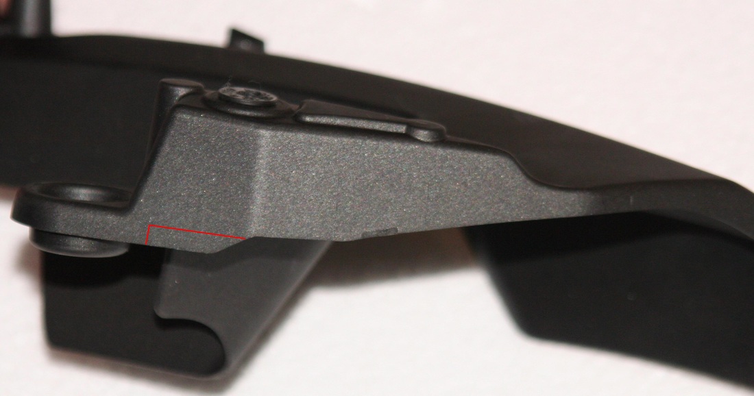
4. By attempting to install the plastic piece, you'll notice that the piece needs a very small amount cut from the section that is against the frame slider bracket (figure E). The cut is minimal and will allow the piece to attach in its normal position over the frame slider offset bracket. The small cut can be made with a box cutter or Dremel tool and the area to be cut is outlined in red in figure E below.
* The piece must attach easily and with both screws, since it is the attaching point for one of the fairing screws.
5. Install all fairing screws.
6. Using the supplied screw, attach the left side frame slider. The bracket normally comes assembled with the left side slider but the slider IS NOT FINAL TORQUED and will fall off while riding if it is not tightened with Loctite on the threads. If using a torque wrench, tighten to 30 ft/lbs. WARNING: THE WASHER MUST BE ON THE SCREW BEFORE INSTALLING THE SLIDERS
Special Notes:
* Caution: Do not use high alkaline based detergents to clean the offset brackets. Use of harsh detergents could cause discoloration of the anodized finish of the brackets.
* If you have a crash and damage one side, you can purchase just the side you need by purchasing directly from our website. Observe whether or not the mounting screws or bracket is bent.
For questions regarding installation, please contact us.
Fork Sliders
Note: This set is installed with the front axle in its normal operating position.
1. Apply medium strength threadlocker compound to one of the mounting screws.
2. Install one of the axle sliders onto the shaft and lightly tighten with a 5mm hex wrench.
3. Insert slider and shaft assembly into the axle from either side.
4. Apply medium threadlocker compound to the other screw and insert through the remaining slider. While holding the opposing slider/shaft firmly in place by hand, insert the slider/screw into the axle and carefully start the screw into the shaft. It may take some careful positioning of the shaft to get the threads started into the shaft.
5. Once the screw has been started and confirmed that proper thread engagement was made, lightly torque the screw.
6. Final tighten the opposing screw with light torque.
Important: Do not over tighten the left or right side screw. For technical assistance, please contact us
Swingarm Spools
The 09-12 ZX6R spools are side specific. The right side base (metal part) is slightly longer than the left. Apply a small amount of medium strength thread locking compound to each screw and tighten with medium torque.
