Fig A
|
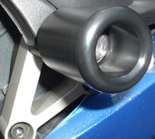
Fig B
|
03-05 Yamaha R6, 06-09 R6S Installation Instructions for:
-Frame Sliders
-Swingarm spools
-Fork Sliders (2005 only)
Tools/Items needed:
Torque wrench
4mm hex key
5mm hex key (2)
8mm hex driver
12mm socket
22mm socket
3/8 or 1/2 ratchet
Blue thread locker
Red thread locker
WARNING: The installation of all parts in these installation instructions must be performed by a qualified motorcycle mechanic who is using the correct tools and who understands the correct use of all tools required to complete the installation.
Frame Sliders
1. Remove the right side mid fairing.
2. Locate and remove (12mm socket) the forward, upper engine mount screw. This is the screw closest to the cowl opening for
the engine. The screw goes through the frame and into the side of the engine cylinder head.
3. Install the slider and bracket assembly using the supplied screw and washer and a 8mm hex driver/ratchet. NOTICE: THE SCREW MUST HAVE A WASHER ON IT. ENSURE THAT THE WASHER IS ON THE SCREW BEFORE THE SCREW IS USED TO ATTACH THE SLIDER. Thread the screw in by hand a couple turns to ensure proper thread engagement.
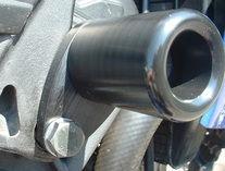
4. Angle the slider and bracket assembly similar to the one pictured (figure A) then tighten. Using a torque
wrench, tighten to the factory torque specification.
Note: Although the slider and bracket assembly comes pre-assembled, it is not pre-torqued. Remove the slider to bracket screw and apply blue thread locker to it, then tighten the screw. 15-20 ft/lbs of torque is recommended. Medium strength (blue) thread locker (on this screw only) is required. If thread locker and proper torque is not used the frame slider could possibly fall off of the bracket while riding due to vibration. NOTICE: THIS SPECIFIC SCREW MUST HAVE A LOCK WASHER AND FLAT WASHER ON IT AND SHOULD ALREADY BE IN PLACE UPON RECEIPT. ENSURE THAT THE WASHERS ARE ON THE SCREW BEFORE THE SCREW IS USED TO ATTACH THE SLIDER.
5. Install the right side mid fairing.
Make certain that the right side is tight before removing the left side screw.
6. On the left, the fairing does not block the mounting point. The screw is accessible with the fairing in place.
Remove the existing engine mount screw. Above is an illustration for the left side. (Figure B)
7. NOTICE: THE SUPPLIED SCREW MUST HAVE A WASHER ON IT. ENSURE THAT THE WASHER IS ON THE SCREW BEFORE THE SCREW IS USED TO ATTACH THE SLIDER. Using a torque wrench, tighten the screw to the factory torque specification.
Caution: Do not use high alkaline based detergents to clean the offset bracket. Use of harsh detergents could
cause discoloration of the anodized finish of the bracket.
Swingarm Spools
1. Locate the spool mount near the rear axle on the swingarm.
2. Apply a small amount of blue thread locker to the supplied screw.
3. Use the 5mm hex key to apply a small amount of torque to the screw to tighten.
4. Repeat for the opposite side.
Fork Sliders
This installation is completed with the front wheel and axle assembled.
1. Remove the front axle bolt using a 22mm socket and 1/2" drive ratchet. The axle pinch screws should be left tight since the axle is not to be removed. The bike does not need to be lifted.
2. If you cannot see through the axle it means that it still has a rubber plug in it. The rubber plug needs to be driven from the axle using a long punch and should be driven out of the opposite side of the axle bolt.
The rubber plug is in place to prevent water/debris from collecting on the axle bolt threads which will also be prevented by the axle slider after installation.
3. Add regular grease or anti-seize grease to the OES supplied axle bolt and tighten with a 22mm socket and a torque wrench applying the factory specified amount of torque.
4. Apply a small amount of red thread locker to the screw of the fork slider with the long base and tighten to the axle slider rod using the 5mm hex key.
5. Insert through the right side of the axle.
6. Apply a small amount of blue thread locker to the screw of the other fork slider and tighten the screw/slider to the rod.
7. Hold the right side slider with one 5mm hex key and tighten the left side using light torque. CAUTION: Too much force can cause the screw to snap or the threads in the rod to strip and a new rod and screw will need to be purchased.
8. Make sure that the assembly does not have any lateral movement.
We recommend keeping and reinstalling the rubber plug just in case the fork sliders are permanently removed.
Please contact us if you have any questions or problems regarding the installation.