07-08 ZX6R Installation Instructions for:
Frame Sliders
Fork Sliders
Swingarm Spools
WARNING: The installation of all parts in these installation instructions must be performed by a qualified motorcycle mechanic who is using the correct tools and who understands the correct use of all tools required to complete the installation.
Tools you will need:
Torque wrench
4mm Hex/Allen key/driver
6mm Hex/Allen driver(an Allen or hex key will not work)
8mm Hex/Allen driver(an Allen or hex key will not work)
Ratchet and extension
Small standard screwdriver
Frame Sliders
Fairings do not need to be modified (cut) in any way. Only the right side mid fairing needs to be partially removed to attach the bracket and slider assembly.
1. Remove the left side engine mount screw with the 6mm hex driver. This screw is visible through the cowl opening in the mid fairing (fig A). The fairings on the left side can remain attached to the bike, since the screw can be accessed easily with the fairing in place.
NOTICE: The engine mount screws are normally very tight from the factory. You will not be able to loosen them with just a 6mm hex key- you will need a hex driver (the type that is used with a 3/8 or 1/2 drive ratchet).
WARNING: THE WASHER MUST BE ON THE SCREW BEFORE INSTALLING THE SLIDERS
2. Now you can install the left side frame slider. The left side slider is longer and does not use an offset bracket like the right side. Tighten the supplied screw with your 8mm hex driver and ratchet w/ extension. Tighten the screw to the factory torque specification (same as factory screw).
3. Partially remove the right side mid fairing by removing the three 4mm hex screws at the lower edge of the mid fairing (fig B, #3,4,and 5), and the two which are up higher and closer to the frame (fig B, # 1 and 2). The other screws at the upper edge of the mid fairing (connecting the mid to the upper fairing, not pictured), do not need to be removed. Also, there are two push pins (fig C) that need to be removed- one at the right side of the triangular opening just behind the front wheel, and one that connects from the bottom of this same opening, beneath the bike. These push pins can be removed with a small flat blade screwdriver. Once these five screws and two push pins are removed, the mid fairing will still be connected to the upper, but will flex out of the way enough to access the engine mount bolt, which is the slider mounting point.
NOTICE! PLEASE READ STEP # 4 VERY CAREFULLY. WHEN PROBLEMS OCCUR WITH THIS FRAME SLIDERS INSTALLATION PROCEDURE, 99% OF THEM ARE CONCERNING THIS NEXT STEP, AND ARE DIRECTLY RELATED TO THE INSTALLER NOT READING OR NOT UNDERSTANDING THIS NEXT STEP. READ CAREFULLY. IF YOU DO NOT UNDERSTAND IT OR YOUR MECHANIC DOES NOT UNDERSTAND IT, CALL US BEFORE PROCEEDING WITH STEP 4.
4. On the right side you will see a castle-type nut on a large stud with a 6mm hex bolt in the center (fig D). This is the lock nut for the engine mount adjuster and does not need to be loosened. At a glance, it may appear that the engine mount screw and the stud are one, but the stud is hollow (fig E) and the engine mount screw runs through it. Remove the screw with your 6mm hex driver. We have found that this screw is normally hard to remove from the factory, and if your hex driver is not of good quality, it could break. We will normally use an impact gun to remove the right side if we install the sliders in our shop. The right side bracket and slider assembly come pre-installed for shipping purposes. You will need to remove the slider from the bracket with your 8mm hex driver and ratchet w/extension.
5. Install the right side bracket (fig F) using the supplied screw- retain the factory screw for later use. Adjust the bracket to a position which will allow the slider to clear the fairing once mounted, then final tighten the bracket to engine mount screw. Tighten the screw to the factory torque specification (same as factory screw). Attach the slider to the offset bracket. Using a torque wrench, tighten to 30 ft/lbs.
6. Reinstall the five screws and the two push pins.
Note: If you have a crash and damage one side, you can purchase just the side you need on this site. Observe whether or not the bolts or bracket is bent.
Frame Sliders
Fork Sliders
Swingarm Spools
WARNING: The installation of all parts in these installation instructions must be performed by a qualified motorcycle mechanic who is using the correct tools and who understands the correct use of all tools required to complete the installation.
Tools you will need:
Torque wrench
4mm Hex/Allen key/driver
6mm Hex/Allen driver(an Allen or hex key will not work)
8mm Hex/Allen driver(an Allen or hex key will not work)
Ratchet and extension
Small standard screwdriver
Frame Sliders
Fairings do not need to be modified (cut) in any way. Only the right side mid fairing needs to be partially removed to attach the bracket and slider assembly.
1. Remove the left side engine mount screw with the 6mm hex driver. This screw is visible through the cowl opening in the mid fairing (fig A). The fairings on the left side can remain attached to the bike, since the screw can be accessed easily with the fairing in place.
NOTICE: The engine mount screws are normally very tight from the factory. You will not be able to loosen them with just a 6mm hex key- you will need a hex driver (the type that is used with a 3/8 or 1/2 drive ratchet).
WARNING: THE WASHER MUST BE ON THE SCREW BEFORE INSTALLING THE SLIDERS
2. Now you can install the left side frame slider. The left side slider is longer and does not use an offset bracket like the right side. Tighten the supplied screw with your 8mm hex driver and ratchet w/ extension. Tighten the screw to the factory torque specification (same as factory screw).
3. Partially remove the right side mid fairing by removing the three 4mm hex screws at the lower edge of the mid fairing (fig B, #3,4,and 5), and the two which are up higher and closer to the frame (fig B, # 1 and 2). The other screws at the upper edge of the mid fairing (connecting the mid to the upper fairing, not pictured), do not need to be removed. Also, there are two push pins (fig C) that need to be removed- one at the right side of the triangular opening just behind the front wheel, and one that connects from the bottom of this same opening, beneath the bike. These push pins can be removed with a small flat blade screwdriver. Once these five screws and two push pins are removed, the mid fairing will still be connected to the upper, but will flex out of the way enough to access the engine mount bolt, which is the slider mounting point.
NOTICE! PLEASE READ STEP # 4 VERY CAREFULLY. WHEN PROBLEMS OCCUR WITH THIS FRAME SLIDERS INSTALLATION PROCEDURE, 99% OF THEM ARE CONCERNING THIS NEXT STEP, AND ARE DIRECTLY RELATED TO THE INSTALLER NOT READING OR NOT UNDERSTANDING THIS NEXT STEP. READ CAREFULLY. IF YOU DO NOT UNDERSTAND IT OR YOUR MECHANIC DOES NOT UNDERSTAND IT, CALL US BEFORE PROCEEDING WITH STEP 4.
4. On the right side you will see a castle-type nut on a large stud with a 6mm hex bolt in the center (fig D). This is the lock nut for the engine mount adjuster and does not need to be loosened. At a glance, it may appear that the engine mount screw and the stud are one, but the stud is hollow (fig E) and the engine mount screw runs through it. Remove the screw with your 6mm hex driver. We have found that this screw is normally hard to remove from the factory, and if your hex driver is not of good quality, it could break. We will normally use an impact gun to remove the right side if we install the sliders in our shop. The right side bracket and slider assembly come pre-installed for shipping purposes. You will need to remove the slider from the bracket with your 8mm hex driver and ratchet w/extension.
5. Install the right side bracket (fig F) using the supplied screw- retain the factory screw for later use. Adjust the bracket to a position which will allow the slider to clear the fairing once mounted, then final tighten the bracket to engine mount screw. Tighten the screw to the factory torque specification (same as factory screw). Attach the slider to the offset bracket. Using a torque wrench, tighten to 30 ft/lbs.
6. Reinstall the five screws and the two push pins.
Note: If you have a crash and damage one side, you can purchase just the side you need on this site. Observe whether or not the bolts or bracket is bent.
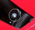
Figure A
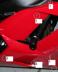
Figure B
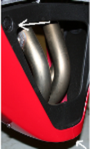
Figure C
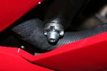
Figure D
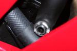
Figure E
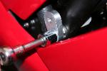
Figure F
Fork Sliders
Note: This set is installed with the front axle in its normal operating position.
1. Apply medium strength thread locker compound to the supplied mounting screw being sure that the washer is on the screw.
2. Install one of the axle sliders onto the supplied shaft and lightly tighten with a 5mm hex wrench.
3. Insert slider and shaft assembly into the axle.
4. Apply medium thread locker compound to the remaining screw and insert through the remaining slider. While holding the
opposing slider/shaft firmly in place by hand, insert the slider/screw into the axle and carefully start the screw into
the shaft. It may take some careful positioning of the shaft to get the screw threads started into the shaft.
5. Once the screw has been started and confirmed that proper thread engagement was made, lightly torque the
screw.
6. Final tighten the opposing screw with light torque.
Important: Do not over tighten the left or right side screw.
For technical assistance, please contact us
Swingarm Spools
Apply a small amount of medium strength (blue threadlocker) to the threads of the supplied screws. Install each with light to medium torque.